 English
 Español

Latest News
Latest News
Latest News
Latest News
Latest News
Latest News
Latest News
Latest News
Latest News
Aluminum fabrication requires careful coordination between the welding power source, filler wire, torch assembly, and wire delivery system. Unlike carbon steel wire, aluminum filler wire is relatively soft and more susceptible to deformation during feeding. A configuration that performs reliably with steel may experience wire buckling, feeding interruptions, or inconsistent arc behavior during aluminum welding.
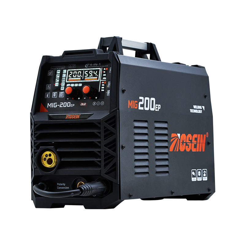
For distributors, fabrication workshops, and industrial equipment buyers, purchasing a aluminum mig welding machine involves more than comparing output current and voltage ranges. The wire-feeding arrangement deserves equal attention because it affects operating stability, accessory compatibility, and routine maintenance requirements.
At OSEIN, we encourage buyers to evaluate the complete feeding configuration before confirming their equipment requirements. Understanding the differences between conventional push feeding, spool guns, and push-pull systems helps purchasing teams communicate their expectations and prepare a suitable equipment package.
1. Why Does Aluminum Welding Require Special Wire-Feeding Support?
Aluminum filler wire has different mechanical properties from solid steel welding wire. Its relatively low stiffness makes it more vulnerable to compression, deformation, and tangling during transportation through the torch cable. Excessive feeding pressure or resistance inside the wire path can interrupt the welding process.
Several common operating problems deserve attention during equipment evaluation:
- Wire birdnesting: Soft aluminum wire may buckle around the drive rolls when feeding resistance becomes excessive.
- Inconsistent wire delivery: Friction inside the liner can cause irregular feeding speeds and interruptions during welding.
- Wire deformation: Excessive drive-roll pressure may flatten or damage the filler wire before it reaches the contact tip.
- Consumable wear: Unsuitable liners, contact tips, and drive rolls may require more frequent inspection or replacement.
These issues can increase downtime and create additional work for operators. Buyers should therefore confirm whether the proposed welding system supports aluminum wire directly or requires additional feeding accessories.
2. Compare Three Wire-Feeding Configurations
Different fabrication environments require different wire delivery arrangements. At OSEIN, we recommend discussing the expected workload, wire diameter, cable length, and production frequency before deciding which configuration should be included in a welding equipment package.
Conventional Push Feeding
A conventional push feeder uses drive rolls inside the welding machine to push filler wire through the liner and welding torch. This arrangement is commonly used for steel welding and may also support certain aluminum applications with suitable modifications.
Buyers considering this configuration should check the following details:
- Whether the wire feeder supports the intended aluminum wire diameter.
- Whether the torch cable can remain sufficiently short and relatively straight.
- Whether dedicated aluminum drive rolls and low-friction liners are available.
- Whether the feeding pressure can be adjusted for softer filler materials.
A push-only arrangement may suit certain light fabrication tasks, particularly with suitable wire diameters and carefully matched accessories. However, long torch cables and small-diameter aluminum wire can create additional feeding challenges. Buyers should request application-specific confirmation rather than assume that a standard steel setup will work equally well.
Spool Gun Feeding
A spool gun places a small filler-wire spool directly on the welding torch. The wire travels only a short distance from the spool to the contact tip, reducing the possibility of buckling inside a long torch liner.
This arrangement is commonly considered for repair workshops, occasional aluminum fabrication, and applications that require relatively short welding sessions.
Several purchasing details require confirmation:
- Connection compatibility: Check whether the welding machine has the required spool gun connection and control interface.
- Spool capacity: Confirm the supported spool dimensions and filler-wire capacity.
- Wire diameter: Verify that the gun supports the intended aluminum wire specifications.
- Trigger control: Check how the spool gun communicates with the machine and whether the standard feeder can be disabled or switched appropriately.
- Replacement components: Ask about compatible contact tips, drive rolls, and other consumables.
A spool gun can simplify aluminum wire delivery, but it also has practical considerations. Its smaller spool requires more frequent replacement than larger workshop wire reels. Buyers handling extended production runs should compare this arrangement with other feeding solutions.
Push-Pull Feeding System
A push-pull system uses two coordinated feeding mechanisms. The machine-side feeder pushes the wire forward, while a motor inside the welding torch pulls it toward the contact tip. This coordinated movement helps maintain more consistent wire delivery across longer torch cables.
Push-pull configurations are worth evaluating for fabrication workshops that regularly process aluminum components or require greater flexibility in torch movement.
Procurement teams should confirm:
- Compatibility between the machine-side feeder and torch motor.
- Supported wire diameters and filler-wire alloys.
- Available torch cable lengths and operating configurations.
- Motor control arrangements and wire speed adjustment methods.
- Maintenance access and replacement motor availability.
Compared with a basic feeding arrangement, a push-pull system involves additional components and configuration requirements. Buyers should compare its operational benefits against the workshop's actual production volume and equipment budget.
3. Check Drive Rolls, Liners, and Contact Tips
The wire-feeding mechanism is not limited to the feeder motor and welding gun. Several smaller components determine how smoothly aluminum wire travels through the system. Purchasing these accessories without checking their material and size compatibility can create avoidable operating problems.
Drive Roll Groove Design
U-groove drive rolls are commonly recommended for aluminum wire. Their groove profile supports the softer wire while reducing the risk of excessive deformation. Highly polished surfaces can also help reduce friction and material buildup.
Conventional V-groove or knurled rolls intended for steel wire should not automatically be used for aluminum. Their gripping characteristics may damage softer filler materials.
Our equipment configuration discussions should therefore cover:
- Drive roll groove type and material.
- Supported wire diameter, such as 0.8 mm, 0.9 mm, or 1.0 mm, subject to model specifications.
- Roll replacement procedures and accessory availability.
- Pressure adjustment requirements for different filler wires.
Liner Material and Cable Compatibility
The liner provides a guided passage for filler wire inside the torch cable. For aluminum applications, low-friction materials such as PTFE or suitable nylon are commonly used to reduce surface resistance and prevent wire damage.
Buyers should pay attention to the following points:
- Liner material must be suitable for the intended aluminum wire.
- Liner dimensions should match the torch and wire diameter.
- Cable length and bending radius should be considered during workshop planning.
- Replacement liners should be available for routine servicing.
Incorrect liner dimensions or excessive cable bending can increase feeding resistance. A compatible liner should be treated as part of the complete torch configuration rather than an interchangeable accessory.
Contact Tip Selection
Contact tips transfer welding current to the filler wire near the arc. Aluminum wire expands under heat, so its contact tip requirements may differ from those of steel wire with the same nominal diameter.
Our recommendation is to verify the contact tip specification against the wire diameter, torch model, and manufacturer's consumable recommendations. Using an unsuitable tip can affect electrical contact and feeding consistency.
4. Match Wire Diameter and Filler Alloy to the Application
Wire-feeding support cannot be evaluated independently of the filler material. Aluminum welding wire is available in different alloys and diameters, and each combination has specific application requirements.
Two commonly discussed filler-wire classifications are ER4043 and ER5356.
- ER4043: An aluminum-silicon filler alloy commonly used for various aluminum fabrication and repair applications. It offers good fluidity during welding and is frequently considered for suitable aluminum base materials.
- ER5356: An aluminum-magnesium filler alloy used in applications requiring different mechanical and corrosion-related properties. Its suitability depends on the base alloy and service conditions.
The correct filler material depends on the parent metal, joint design, required mechanical properties, and applicable welding procedure. Buyers should provide this information before requesting a machine and accessory quotation.
Wire diameter also affects feeder compatibility. Common workshop wire sizes include 0.8 mm, 0.9 mm, 1.0 mm, and larger diameters, although actual availability depends on the machine and feeding assembly.
We suggest preparing a wire specification sheet containing:
- Aluminum alloy classification.
- Wire diameter and spool dimensions.
- Expected welding current and wire feed speed range.
- Workpiece alloy and material thickness.
- Typical joint types and welding positions.
These details help our team evaluate the required feeding configuration and identify accessories that match the intended application.
5. Confirm Shielding Gas and Electrical Requirements
Stable wire feeding is only part of the equipment preparation process. Shielding gas delivery and electrical compatibility also affect the welding setup.
Shielding Gas Configuration
Pure argon is commonly used for conventional aluminum MIG welding applications. The gas supply system should include compatible regulators, flowmeters, hoses, and connections.
Purchasing teams should verify:
- Gas type and purity requirements.
- Regulator inlet and outlet connections.
- Flow adjustment range and gas hose compatibility.
- Torch nozzle and gas diffuser compatibility.
Actual gas flow settings depend on torch design, nozzle size, welding position, and surrounding conditions. The recommended settings should be confirmed through the applicable welding procedure.
Power Supply and Output Range
Aluminum's thermal conductivity and oxide layer influence welding parameter requirements. The machine's input voltage, output current, duty cycle, and available wire speed range should correspond to the intended workpiece thickness and production schedule.
Before confirming an order, buyers should provide the following electrical information:
- Available single-phase or three-phase power supply.
- Input voltage and frequency requirements.
- Required welding current range.
- Expected operating duration and production frequency.
- Available workshop electrical capacity.
These specifications allow OSEIN to review equipment suitability and discuss the available machine configurations with buyers.
6. Evaluate Supplier Support Beyond the Machine Configuration
Equipment purchasing also involves communication, technical documentation, accessory supply, and after-sales arrangements. A suitable machine configuration may still create operational difficulties if buyers cannot obtain clear compatibility information or replacement components.
At OSEIN, we recommend discussing the following service requirements during the quotation stage:
- Technical documentation: Request operating manuals, connection diagrams, and relevant machine specifications.
- Accessory identification: Confirm the model references for compatible spool guns, push-pull torches, liners, and drive rolls.
- Configuration consultation: Provide material information and production requirements so our team can review the proposed setup.
- Replacement component supply: Discuss the availability of consumables and service parts for ongoing workshop operations.
- Operating guidance: Clarify available technical assistance for wire installation, feeding pressure adjustment, and routine equipment inspection.
Clear communication at this stage helps buyers understand the complete equipment package and prepare their maintenance arrangements before the machine enters service.
7. A Practical Purchasing Checklist for Aluminum MIG Equipment
Procurement teams can use the following checklist to organize technical discussions and compare quotations from welding equipment suppliers.
| Evaluation Item | Details to Confirm | Purchasing Purpose |
| Feeding system | Push, spool gun, or push-pull | Match wire delivery to production requirements |
| Wire diameter | Supported aluminum wire sizes | Check feeder and torch compatibility |
| Drive rolls | U-groove design and size | Reduce wire deformation |
| Torch liner | PTFE, nylon, or other suitable material | Reduce friction along the wire path |
| Contact tips | Compatible diameter and torch model | Maintain suitable electrical contact |
| Shielding gas | Gas type, regulator, and connections | Prepare the gas delivery system |
| Power supply | Input voltage, current, and duty cycle | Match the machine to workshop conditions |
| Supplier services | Documentation, technical guidance, and spare parts | Support equipment operation and maintenance |
Buyers can also request a detailed quotation that separates standard machine accessories, optional feeding equipment, and consumables. This makes it easier to identify additional costs and compare different equipment configurations on a consistent basis.
Discuss Your Aluminum Welding Requirements with OSEIN
Reliable aluminum wire feeding depends on the coordination of the welding machine, feeder mechanism, torch assembly, consumables, and filler material. Purchasing decisions based solely on the machine's rated output may overlook important accessory requirements that affect daily workshop operations.
At OSEIN, we provide MIG/MAG welding equipment for different fabrication requirements and support buyers with product configuration discussions. Our team can help review machine specifications, accessory compatibility, and application requirements according to the intended welding process.
To help us understand your project, prepare the following information before contacting our team:
- Base material and aluminum alloy.
- Workpiece thickness and joint requirements.
- Filler-wire classification and diameter.
- Preferred wire-feeding arrangement.
- Available workshop power supply and expected workload.
Share these details with OSEIN through osein-welding.com to discuss a suitable equipment configuration. A clear understanding of wire-feeding requirements helps your purchasing team plan the complete welding setup, coordinate accessory orders, and prepare for long-term equipment operation.